During the implementation of the project, several interruptions may be required, but if each of them has the highest priority, then in fact none of the functions will have it. For the same reason, it is not recommended to use more than a dozen interrupts.
Handlers should be applied only to those processes that have maximum sensitivity to time intervals. Do not forget that while the program is in the interrupt handler, all other interrupts are disabled. A large number of interruptions leads to a deterioration in their response.
At the moment when one interrupt is active, and the rest are turned off, two important nuances arise that the circuitry should take into account. Firstly, the interruption time should be as short as possible.
This will allow you to skip all other scheduled interrupts. Secondly, when processing interrupts, program code should not require activity from other interrupts. If this is not prevented, then the program will simply freeze.
Do not use long processing in loop () , it is better to develop code for the interrupt handler with the volatile variable set. She will tell the program that further processing is not needed.
If a function call Update () if it is necessary, then it will be necessary to check the state variable first. This will determine if further processing is necessary.
Before you start configuring the timer, you should check the code. Timers Anduino should be attributed to limited resources, because there are only three of them, and they are used to perform a variety of functions. If you get confused with the use of timers, then a number of operations may simply stop working.
What functions does this or that timer operate with?
For the Arduino Uno microcontroller, each of the three timers has its own operations.
So Timer0 responsible for PWM on the fifth and sixth pin, functions millis () , micros () , delay () .
Another timer is Timer1, used with PWM on the ninth and tenth pin, with libraries WaveHC and Servo.
Timer2 works with PWM on 11 and 13 pins, as well as with Tone.
The circuit designer must take care of the safe use of shared data. After all, interruption stops all processor operations for a millisecond, and data exchange between loop () and interrupt handlers should be constant. A situation may arise when the compiler, in order to achieve its maximum performance, starts optimizing the code.
The result of this process will be to save copies of the main code variables in the register, which will ensure the maximum access speed to them.
The disadvantage of this process may be the substitution of real values \u200b\u200bwith stored copies, which can lead to loss of functionality.
To prevent this, use the variable voltatile , which will help prevent unnecessary optimizations. When using large arrays that require loops for updates, you need to disable interrupts at the time of these updates.
When you install this program, you will be surprised - how similar it is to the Arduino IDE. Do not be surprised, both programs are made on the same engine.
The application has a lot of features, including a library Serial, so we can link the data transfer between the board and.
Run the Arduino IDE and select the simplest example of data output to Serial port:
Void setup () (Serial.begin (9600);) void loop () (Serial.println ("Hello Kitty!"); // wait 500 milliseconds before the next send delay (500);)
Run the example and make sure the code works.
Data retrieval
Now we want to get the same text in. We start a new project and write the code.
The first step is to import the library. Go to Sketch | Import Library | Serial. A line will appear in the sketch:
Import processing.serial. *; Serial serial; // create a serial port object String received; // data received from the serial port void setup () (String port \u003d Serial.list (); serial \u003d new Serial (this, port, 9600);) void draw () (if (serial.available ()\u003e 0) (// if there is data, received \u003d serial.readStringUntil ("\\ n"); // read the data) println (received); // display the data in the console)
In order to receive data from the serial port, we need a class object Serial. Since we send data of type String with Arduino, we need to get the string in Processing as well.
In method setup () You need to get an available serial port. This is usually the first available port from the list. After that we can configure the object Serialby specifying the port and data transfer rate (it is desirable that the speeds coincide).
It remains to reconnect the board, run the sketch from Processing and observe the incoming data in the application console.
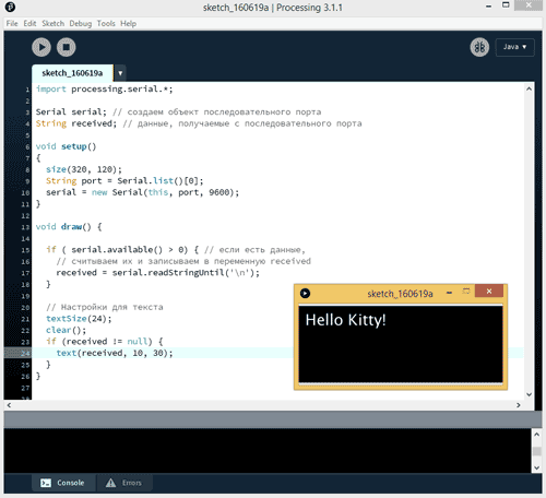
Processing allows you to work not only with the console, but also create standard windows. Rewrite the code.
Import processing.serial. *; Serial serial; // create a serial port object String received; // data received from the serial port void setup () (size (320, 120); String port \u003d Serial.list (); serial \u003d new Serial (this, port, 9600);) void draw () (if (serial .available ()\u003e 0) (// if there is data, // read it and write it to the variable received received \u003d serial.readStringUntil ("\\ n");) // Text settings textSize (24); clear (); if (received! \u003d null) (text (received, 10, 30);))
Run the example again and see a window with an inscription that is redrawn in one place.
Thus, we learned how to receive data from Arduino. This will allow us to draw beautiful graphs or create programs for monitoring the readings of sensors.
Sending data
We can not only receive data from the board, but also send data to the board, forcing us to execute commands from the computer.
Suppose we will send the character "1" from Processing. When the board detects the sent symbol, turn on the LED on port 13 (built-in).
The sketch will be similar to the previous one. For example, create a small window. When we click in the window area, we will send "1" and duplicate it in the console for verification. If there are no clicks, the command "0" is sent.
Import processing.serial. *; Serial serial; // create a serial port object String received; // data received from the serial port void setup () (size (320, 120); String port \u003d Serial.list (); serial \u003d new Serial (this, port, 9600);) void draw () (if (mousePressed \u003d\u003d true) (// if we clicked with the mouse within the window serial.write ("1"); // send 1 println ("1");) else (// if there was no click serial.write ("0" ); // send 0))
Now let's write a sketch for Arduino.
Char commandValue; // data received from the serial port int ledPin \u003d 13; // built-in LED void setup () (pinMode (ledPin, OUTPUT); // data output mode Serial.begin (9600);) void loop () (if (Serial.available ()) (commandValue \u003d Serial.read ( );) if (commandValue \u003d\u003d "1") (digitalWrite (ledPin, HIGH); // turn on the LED) else (digitalWrite (ledPin, LOW); // otherwise turn it off) delay (10); // delay before next reading of data)
We start both sketches. We click inside the window and notice that the LED lights up. You can not even click, but hold the mouse button pressed - the LED will light constantly.
Data exchange
Now let's try to combine both approaches and exchange messages between the board and the application in two directions.
For maximum efficiency, add a Boolean variable. As a result, we no longer need to constantly send 1 or 0 from Processing and the serial port is unloaded and does not transmit unnecessary information.
When the board detects the unit sent, we change the Boolean value to the opposite relative to the current state ( Low on the High and vice versa). IN else we use the string "Hello Kity", which we will only send if we do not find "1".
Function establishContact () sends the string that we expect to receive in Processing. If the answer comes, then Processing can get the data.
Char commandValue; // data received from the serial port int ledPin \u003d 13; boolean ledState \u003d LOW; // control the state of the LED void setup () (pinMode (ledPin, OUTPUT); Serial.begin (9600); establishContact (); // send the byte for the contact while the receiver answers) void loop () (// if you can read the data if (Serial.available ()\u003e 0) (// read data commandValue \u003d Serial.read (); if (commandValue \u003d\u003d "1") (ledState \u003d! ledState; digitalWrite (ledPin, ledState);) delay (100) ;) else (// Send back Serial.println ("Hello Kitty");) delay (50);) void establishContact () (while (Serial.available ()<= 0) { Serial.println("A"); // отсылает заглавную A delay(300); } }
Go to the Processing sketch. We will use the method serialEvent (), which will be called every time a certain character is detected in the buffer.
Add a new boolean variable firstContact, which allows you to determine if there is a connection with Arduino.
In method setup () add line serial.bufferUntil ("\\ n");. This allows you to store incoming data in the buffer until we find a specific character. In this case, return (\\ n), since we send Serial.println () from Arduino. "\\ n" in the end means that we are activating a new line, that is, it will be the last data that we will see.
Since we are constantly sending data, the method serialEvent () performs cycle tasks draw (), then you can leave it empty.
Now consider the main method serialEvent (). Each time we go to a new line (\\ n), this method is called. And each time the following sequence of actions is carried out:
- The incoming data is read;
- It is checked whether they contain any values \u200b\u200b(that is, whether an empty data array or "zero" was passed to us);
- We remove spaces;
- If the first time we got the necessary data, we change the value of the boolean variable firstContact and inform Arduino that we are ready to receive new data;
- If this is not the first reception of the required data type, display them in the console and send the data about the click that occurred to the microcontroller;
- We inform Arduino that we are ready to receive a new data packet.
When connecting and starting, the phrase "Hello Kitty" should appear in the console. When you click the mouse in the Processing window, the LED on pin 13 will turn on and off.
In addition to Processing, you can use PuTTy programs or write your program in C # using ready-made classes for working with ports.
04.Communication: Dimmer
An example demonstrates how you can send data from a computer to a board to control the brightness of the LED. Data comes in separate bytes from 0 to 255. Data can come from any program on the computer that has access to the serial port, including Processing.
For example, you need a standard circuit with a resistor and an LED on pin 9.
Sketch for Arduino.
Const int ledPin \u003d 9; // LED on pin 9 void setup () (Serial.begin (9600); // set the mode to pinMode (ledPin, OUTPUT);) void loop () (byte brightness; // check if there is data from the computer if (Serial.available ()) (// read the last received bytes from 0 to 255 brightness \u003d Serial.read (); // set the brightness of the LED analogWrite (ledPin, brightness);))
Code for Processing
Import processing.serial. *; Serial port; void setup () (size (256, 150); println ("Available serial ports:"); println (Serial.list ()); // Uses the first port in this list (number 0). Change this to select the port // corresponding to your Arduino board. The last parameter (eg 9600) is the // speed of the communication. It has to correspond to the value passed to // Serial.begin () in your Arduino sketch. port \u003d new Serial (this, Serial.list (), 9600); // If you know the name of the port used by the Arduino board, then explicitly specify // port \u003d new Serial (this, "COM1", 9600);) void draw () ( // draw a black to white gradient for (int i \u003d 0; i
We launch and move the mouse over the created window in any direction. When moving to the left, the brightness of the LED will decrease, when moving to the right, it will increase.

04.Communication: PhysicalPixel (Light the LED with the mouse)
Let's change the task a bit. We will hold the mouse over the square and send the “H” (High) symbol to light the LED on the board. When the mouse leaves the area of \u200b\u200bthe square, then send the symbol "L" (Low) to turn off the LED.
Code for Arduino.
Const int ledPin \u003d 13; // pin 13 for the LED int incomingByte; // variable for receiving data void setup () (Serial.begin (9600); pinMode (ledPin, OUTPUT);) void loop () (// if there is data if (Serial.available ()\u003e 0) (// read byte in the buffer incomingByte \u003d Serial.read (); // if it is a character H (ASCII 72), then turn on the LED if (incomingByte \u003d\u003d "H") (digitalWrite (ledPin, HIGH);) // if it is a character L ( ASCII 76), then turn off the LED if (incomingByte \u003d\u003d "L") (digitalWrite (ledPin, LOW);)))
Code for Processing.
Import processing.serial. *; float boxX; float boxY; int boxSize \u003d 20; boolean mouseOverBox \u003d false; Serial port; void setup () (size (200, 200); boxX \u003d width / 2.0; boxY \u003d height / 2.0; rectMode (RADIUS); println (Serial.list ()); // Open the port that the Arduino board is connected to (in this case # 0) // Make sure to open the port at the same speed Arduino is using (9600bps) port \u003d new Serial (this, Serial.list (), 9600);) void draw () (background (0 ); // If the cursor is over the square if (mouseX\u003e boxX - boxSize && mouseX boxY - boxSize && mouseY
04.Communication: Graph
If in the previous example we sent data from the computer to the board, now we will perform the inverse task - we will receive data from the potentiometer and display it in a graph.
Generally speaking, Arduino does not support true task parallelization, or multithreading. But it is possible at each repetition of the cycle loop () instruct the microcontroller to check whether it is time to complete some additional, background task. In this case, the user will think that several tasks are performed simultaneously.
For example, let's blink an LED at a given frequency and simultaneously make sounds from the piezo-emitter growing and fading like a siren. We have already connected the LED and the piezo emitter to the Arduino more than once. Let's assemble the circuit as shown in the figure.
If you connect the LED to a digital output other than "13", do not forget about a current limiting resistor of about 220 ohms.
2 LED and piezo emitter controlusing the delay () operator
Let's write such a sketch and upload it to Arduino.
Const int soundPin \u003d 3; / * declare a variable with the pin number to which the piezoelectric element is connected * / const int ledPin \u003d 13; // declare a variable with the pin number of the LED void setup () ( pinMode (soundPin, OUTPUT); // declare pin 3 as an output. pinMode (ledPin, OUTPUT); // declare pin 13 as an output. } void loop () ( // Sound control: tone (soundPin, 700); // produce sound at a frequency of 700 Hz delay (200); tone (soundPin, 500); // at a frequency of 500 Hz delay (200); tone (soundPin, 300); // at a frequency of 300 Hz delay (200); tone (soundPin, 200); // at a frequency of 200 Hz delay (200); // LED control: digitalWrite (ledPin, HIGH); // light delay (200); digitalWrite (ledPin, LOW); // extinguish delay (200); }
After switching on, it is clear that the sketch is not performed exactly as we need: until the siren is fully operated, the LED will not blink, and we would like the LED to blink during the sound of a siren. What is the problem here?
The fact is that in the usual way this problem cannot be solved. Tasks are performed by the microcontroller strictly sequentially. Operator delay () delays the execution of the program for a specified period of time, and until this time expires, the following program commands will not be executed. Because of this, we cannot set different execution times for each task in the cycle loop () programs. Therefore, you need to somehow simulate multitasking.
3 Parallel processeswithout operator "delay ()"
The option in which Arduino will perform tasks pseudo-in parallel was proposed by Arduino developers. The essence of the method is that with each repetition of the cycle loop () we check whether it is time to blink an LED (to perform a background task) or not. And if it is, then invert the state of the LED. This is a kind of operator bypass option. delay ().
Const int soundPin \u003d 3; // variable with the number of the piezoelectric element pin const int ledPin \u003d 13; // variable with the pin number of the LED const long ledInterval \u003d 200; // LED flashing interval, ms. int ledState \u003d LOW; // initial state of the LED unsigned long previousMillis \u003d 0; // store the time of the previous LED operation void setup () ( pinMode (soundPin, OUTPUT); // set pin 3 as an output. pinMode (ledPin, OUTPUT); // set pin 13 as an output. } void loop () ( // Sound control: tone (soundPin, 700); delay (200); tone (soundPin, 500); delay (200); tone (soundPin, 300); delay (200); tone (soundPin, 200); delay (200); // Flashing LED: // time since the Arduino was turned on, ms: unsigned long currentMillis \u003d millis (); // If the time to blink has come, if (currentMillis - previousMillis\u003e \u003d ledInterval) (previousMillis \u003d currentMillis; // then remember the current time if (ledState \u003d\u003d LOW) (// and invert the status of the LED ledState \u003d HIGH;) else (ledState \u003d LOW;) digitalWrite (ledPin, ledState); // switch the status of the LED) }
A significant drawback of this method is that the code section in front of the LED control unit must execute faster than the interval of flashing of the LED "ledInterval". Otherwise, the blinking will occur less often than necessary, and we will not get the effect of parallel execution of tasks. In particular, in our sketch, the duration of the change in the sound of the siren is 200 + 200 + 200 + 200 \u003d 800 ms, and we set the interval for blinking the LED to 200 ms. But the LED will blink with a period of 800 ms, which is 4 times more than what we set.
In general, if the code uses the operator delay (), in this case it is difficult to imitate pseudo-parallelism, therefore it is advisable to avoid it.
In this case, it would also be necessary to check for the siren sound control unit whether the time has come or not, and not to use delay (). But this would increase the amount of code and degrade the readability of the program.
4 Using the ArduinoThread Libraryto create parallel threads
To solve the problem, we will use a wonderful library ArduinoThread, which allows you to easily create pseudo-parallel processes. It works in a similar way, but eliminates the need to write time-checking code - you need to complete the task in this cycle or not. This reduces the amount of code and improves the readability of the sketch. Let's check the library in action.

First of all, download the library archive from the official site and unzip it into a directory libraries / Arduino IDE development environment. Then rename the folder ArduinoThread-master in ArduinoThread.
The wiring diagram will remain the same. Only the program code will change.
#include
In the program, we create two threads - ledThread and soundThread, each performs its operation: one flashes an LED, the second controls the sound of the siren. In each iteration of the loop for each thread, we check whether the time has come for its execution or not. If it arrives, it is launched for execution using the method run (). The main thing is not to use the operator delay (). The code provides more detailed explanations.

We load the code into the memory of Arduino, run it. Now everything works exactly as it should!
This article will address the issues of parallel and serial connection of several slaves to the SPI bus, serial connection of shift registers, work with a dual 7-segment display, the implementation of independent processes in Arduino. As a result, we will make a little scheme in which a snake will run along a double 7-segment, and on the other, single, seconds will be ticking at this time.
we met with the SPI bus and learned that to connect the slave to the master, 4 wires are needed. However, if there are more than one slave device, we already have interesting options.
Parallel connection of devices to the SPI bus
When connected in parallel, several slaves use common wires SCLK, MOSI and Misowhile each slave has its own line SS
. Presenter defines exchange deviceby forming a low signal on his SS
.
It is seen that to connect n devices required n lines SS
, that is, for the functioning of the SPI environment with n followers need to be allocated for this n + 3 feet of the microcontroller.
Serial connection of devices to the SPI bus
When connecting devices in series, they use common wires SCLK and SS
, and the output of one is connected to the input of the other. MOSI the master is connected to the first device, and Miso - to the last. That is, for the master on the SPI bus, this is like one device.
Such a connection allows us to build, for example, from two 8-bit shift registers one 16-bit one, which we will do now.
It remains to note the charm of such a connection: connect at least 3, at least 8 devices, it takes only 4 legs on the controller.
Serial connection of two shift registers
Once again, look at the shift register 74HC595:
We remember that DS - there is a serial input pin, and Q0-Q7 serial output pins. Q7Swhich we did not use when we had only one register in the circuit is the serial output of the register. It finds its application when we transfer more than 1 byte to the registers. Through this pin, all bytes intended for subsequent registers are pushed sequentially, and the last byte transmitted will remain in the first register.

By connecting pin Q7S of one first register to pin DS of the second (and so on, if necessary), we obtain a double (triple, etc.) register.
Connecting a dual 7-segment display
A dual 7-segment display is usually a device with 18 legs, 9 for each character. Let's take a look at the circuit (my display is marked LIN-5622SR and there is a high probability that its connection scheme will be unique):

This is a display with a common anode, which indicates the need for a high level of TTL to be supplied to com1 and com2, and a low level for the corresponding leg to ignite the diode. If you have a display with a common cathode, you need to do the opposite!
Connect the display, as shown in the diagram:

We connect the left display to the first register: 1A to the leg Q0, 1B to the leg Q1, 1C to the leg Q2, etc. The common contact com1 is connected to ground. We do the same with the right display: 2A to the foot Q0, 2B to the foot Q1, etc., the common contact com2 - to the ground.
The circuit will not look like the one in the picture, if the location of the terminals on the display differs from mine, here you just need to be careful when connecting. If the display is with a common cathode, then com1 and com2 are connected to power!
Simple snake on a dual 7-segment display
So, we learned to light the numbers on a single-character display last time, and today we will draw a snake on a two-character display. To begin with, we will make a simple snake, which consists of three segments and runs in a circle.
Our cycle will consist of eight frames, on each of which certain three LEDs will light up. In the first frame, 1E, 1F, 1A will burn (see diagram), in the second - 1F, 1A, 2A, in the third - 1A, 2A, 2B and so on, in the eighth - 1D, 1E, 1F.
Again, for convenience, we will compile a byte label, remembering that by default bits are transmitted starting from the oldest, i.e. 2h.
Frame | 1 abcd efgh | 2 abcd efgh | hex |
0111 0011 | 1111 1111 | EC FF |
|
0111 1011 | 0111 1111 | ED EF |
|
0111 1111 | 0011 1111 | Ef cf |
|
1111 1111 | 0001 1111 | Ff 8f |
|
1111 1111 | 1000 1111 | Ff 1f |
|
1110 1111 | 1100 1111 | 7F 3F |
|
1110 0111 | 1110 1111 | 7E 7F |
|
1110 0011 | 1111 1111 | 7C FF |
The leader should set the low (active) level on the wire SS , transfer two bytes, and release the wire. At this moment, a snap will occur, each register will be written by byte, two characters will light up.
#include<SPI .h\u003e // connect the SPI library
enum (reg \u003d 9); // select the lineSS
register on the 9th pin of Arduino
void setup
()
{
SPI .begin (); // initialize SPI
// translate the pin selected for transfer to output mode
pinMode (reg, OUTPUT);
}
void loop
()
{
// Fill the array with bytes to be transmitted
static uint8_t digit \u003d
(0xFF, 0xCE, 0xFF, 0xDE, 0xFC, 0xFE, 0xF8,0xFF,
0xF1,0xFF, 0xF3,0xF7,0xF7,0xE7,0xFF, 0xC7};
// pass two bytes from the array and snap the registers
for (int i \u003d 0; i<16;i+=2){
digitalWrite (reg, LOW);
SPI .transfer (digit [i]);
SPI .transfer (digit);
digitalWrite (reg, HIGH);
delay (80); // pause between frames
}
}
Video of the program:
Parallel Processes in Arduino
Why are Arduino developers focusing on the Blink without delay example?
Usually the Arduino program is linear - first it does one thing, then another. In the example above, we used the function delay (80)so that each frame is drawn 80 milliseconds after the previous one. However, after all these 80 milliseconds the processor does nothing and does not allow anyone to do anything! To start two or more parallel processes, we need to change the concept of building a program, abandoning delay () .
The core of our new design will be a timer. The timer will count the time, and we will make this or that event happen at certain intervals. For example, a clock display will tick every second, and an LED will flash every 0.86 seconds.
In Arduino there is a thing that counts the time from the beginning of the program, it is called millis (). With its help, "parallelization" of tasks is organized.
Final project: a clock and a cunning snake
We assemble the following scheme:

From the point of view of the master, the left and middle registers work as one device, and the right register - as another. It can be seen that these two devices use the same wire SCLK (13th pin of Arduino, wire is shown in orange) and MOSI (11th pin, yellow), SS
used different (pins 8 and 9, green). The connection of 7-segment displays to the registers is shown for my specific models and probably will not match yours.
This time we will make our snake trickier: it will run through all segments the same way as a wolf riding a motorcycle in the Well Wait! Series, which begins with the fact that he rolls this motorcycle out of the garage and puts on his helmet .
The byte sequence for this snake will be:
Static uint8_t snake \u003d
Now the gist: function millis () sits and counts milliseconds from the start. At the beginning of each loop, we remember the value millis ()to variable timer.Plant variables snakeTimerPrev and digitTimerPrevthat will store the moment of the previous event: for snakeTimerPrev is the inclusion of the previous snake animation frame, for digitTimerPrev - inclusion of the previous digit. As soon as the difference is the current time ( timer) and previous ( snakeTimerPrevor digitTimerPrev) becomes equal to the specified period (in our case - 80 and 1000 ms, respectively), we transfer the next frame / byte.
Thus,
- every 80 ms the controller will lower the signal on the line SS dual display, transmit two bytes and release the line.
- every second the controller will lower the signal on the line SS single display, transmit one byte and let go of the line.
#include<SPI .h\u003e
enum (snakePin \u003d 9, digitPin \u003d 8);
unsigned long timer \u003d 0, snakeTimerPrev \u003d 0, digitTimerPrev \u003d 0;
int i \u003d 0, j \u003d 0;
void setup
()
{
SPI.begin ();
pinMode (digitPin, OUTPUT);
pinMode (snakePin, OUTPUT);
}
void loop
()
{
static uint8_t digit \u003d
(0xC0.0xF9.0xA4.0xB0.0x99.0x92.0x82.0xF8,
0x80.0x90.0x88.0x83.0xC6.0xA1.0x86.0x8E);
static uint8_t snake \u003d
(0xFF, 0x9E, 0xFF, 0xDC, 0xFF, 0xF8,0xFF, 0xF1,
0xFF, 0xE3,0xFF, 0xA7,0xBF, 0xAF, 0xBD, 0xBF,
0xBC, 0xFF, 0xDC, 0xFF, 0xCE, 0xFF, 0xC7,0xFF,
0xE3,0xFF, 0xB3,0xFF, 0xBB, 0xBF, 0xBF, 0x9F);
timer \u003d millis ();
if (timer-snakeTimerPrev\u003e 80) (
digitalWrite (snakePin, LOW);
SPI.transfer (snake [j]);
SPI.transfer (snake);
digitalWrite (snakePin, HIGH);
j<30 ? j+=2: j=0;
snakeTimerPrev \u003d timer;
}
if (timer-digitTimerPrev\u003e 1000) (
digitalWrite (digitPin, LOW);
SPI.transfer (digit [i]);
Instruction manual
Generally speaking, Arduino does not support true task parallelization, or multithreading.
But it is possible at each repetition of the loop () loop to indicate to check whether it is time to complete some additional, background task. In this case, the user will think that several tasks are performed simultaneously.
For example, let’s blink at a given frequency and simultaneously make sounds from the piezo-emitter growing and fading like a siren.
Both the LED and we have repeatedly connected to the Arduino. Let's assemble the circuit as shown in the figure. If you connect the LED to a digital output other than "13", do not forget about a current limiting resistor of about 220 ohms.
Let's write such a sketch and upload it to Arduino.
After the board, it is clear that the sketch is not performed exactly as we need: until the siren is fully operated, the LED will not blink, and we would like the LED to be ON while the siren is playing. What is the problem here?
The fact is that in the usual way this problem cannot be solved. Tasks are performed by the microcontroller strictly sequentially. The statement "delay ()" delays the execution of the program for the specified period of time, and until this time has expired, the following program commands will not be executed. Because of this, we cannot set different execution times for each task in the program loop () loop.
Therefore, you need to somehow simulate multitasking.

The option in which Arduino will perform tasks pseudo-in parallel was proposed by Arduino developers in the article https://www.arduino.cc/en/Tutorial/BlinkWithoutDelay.
The essence of the method is that at each repetition of the loop () cycle, we check whether it is time to blink an LED (to perform a background task) or not. And if it is, then invert the state of the LED. This is a peculiar way to bypass the "delay ()" operator.
A significant drawback of this method is that the code section in front of the LED control unit must execute faster than the interval of flashing of the LED "ledInterval". Otherwise, the blinking will occur less often than necessary, and we will not get the effect of parallel execution of tasks. In particular, in our sketch, the duration of the change in the sound of the siren is 200 + 200 + 200 + 200 \u003d 800 ms, and we set the interval for blinking the LED to 200 ms. But the LED will blink with a period of 800 ms, which is 4 times different from what we set. In general, if the code uses the "delay ()" operator, then it is difficult to simulate pseudo-parallelism, so it is advisable to avoid it.
In this case, it would also be necessary to check for the siren sound control unit whether the time has come or not, and not to use "delay ()". But this would increase the amount of code and degrade the readability of the program.

To solve this problem, we will use the wonderful ArduinoThread library, which allows you to easily create pseudo-parallel processes. It works in a similar way, but eliminates the need to write time-checking code - you need to complete the task in this cycle or not. This reduces the amount of code and improves the readability of the sketch. Let's check the library in action.
First, download the library archive from the official site https://github.com/ivanseidel/ArduinoThread/archive/master.zip and unzip it into the "libraries" directory of the Arduino IDE development environment. Then rename the ArduinoThread-master folder to ArduinoThread.

The wiring diagram will remain the same. Only the program code will change. Now it will be the same as on the sidebar.
In the program we create two streams, each performs its own operation: one flashes an LED, the second controls the sound of the siren. In each iteration of the loop for each thread, we check whether the time has come for its execution or not. If it comes, it is launched for execution using the "run ()" method. The main thing is not to use the "delay ()" operator.
The code provides more detailed explanations.
We load the code into the memory of Arduino, run it. Now everything works exactly as it should!