From time to time we all face the problem of an insufficient signal level of the router. The signal is unstable at some points, often disappears or not at all. This is noticeable in rooms with a large area: in the country, in a private house, in a recreation center, in an apartment in which there is more than one room. In this article, we describe solutions to this problem.
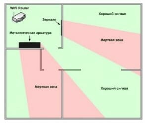
Figure 1. The WiFi coverage area of \u200b\u200bthe router network in a typical apartment (router next to the front door).
We produce passive and active antennas, including for data networks, WiFi. In this article, we are not so much interested in wireless access issues as in ways to increase WiFi coverage. Note that we do not consider specific options for creating special “powerful” access points. Everything is only within the framework of standards and norms adopted in the Russian Federation.
In our experience, the router is usually placed: next to the front door, in the corridor behind the cabinet, or in the distribution panel. In such cases, the area of \u200b\u200bthe apartment is not uniformly covered by the WiFi network. Depending on the layout of the apartment, the far rooms, the kitchen, the loggia are outside the zone of sustainable coverage. (Example in Figure 1)
The same situation is true for a private house. The area of \u200b\u200bthe house is usually larger, and the Internet is needed not only indoors, but also outside - at the barbecue area, pool, on the playground. Here the problem is more serious.

Figure 2. WiFi coverage area of \u200b\u200bthe router network in a country house
Figures 1 and 2 show examples of WiFi coverage, green areas with a good network level are highlighted in green, red with a low level, which often does not allow you to work normally on the Internet. Note that the WiFi signal, being a radio wave, spreads better in free space, so the walls and other partitions in the room will weaken it and, as a result, reduce the level of the signal that passed through them.
The problem is identified - insufficient coverage of the WiFi network in the room. Let's see why this is happening. The router’s standard antenna has a circular radiation pattern - it radiates WiFi in all directions. Including towards your neighbors, which is usually pointless and not necessary. At the same time, the antenna’s own gain is relatively small, as a result of which, such an antenna has insufficient efficiency. As a result, the coverage area of \u200b\u200bthe WiFi signal is small.

Figure 3. Directivity pattern of a standard router antenna (f \u003d 2.45 GHz)
Figure 3 shows the radiation pattern of an external antenna of a standard router, calculated in a physical simulator. A dipole is used as an antenna.
How to improve WiFi coverage
The first thing that comes to mind is to replace the router with another one. Buy a device with a more powerful external antenna or with several antennas. If you have an outdated router model, then it's worth a try. Be prepared that this will require additional costs, and a positive result is not guaranteed at all. Most likely, the picture will improve, but the problem will not be resolved (Fig. 4-5).

Figure 4. A router with two external antennas.

Figure 5. A router with three external antennas.
The next way is to use an active WiFi repeater, it is also called a WiFi repeater. This device is just designed to increase the range of a WiFi network. A great way, often allowing you to solve the problem in the bud. But he has also disadvantages:
- prices from one and a half thousand rubles and above;
- the need for customization;
- limited area of \u200b\u200buse.
And this is not all: the repeater will again receive a signal from all sides and radiate around. That is, if we have an “unreached” corner of the apartment far, then two or even three repeaters will be required. It would be great to concentrate the signal in a given direction, but it won’t work out - the built-in repeater antennas have a pie chart. Repeaters with a jack for an external antenna we did not meet.
It is worth mentioning another feature of the WiFi repeater - the presence of 220V mains power. Not all people are ready to leave some devices connected to the network when leaving home. And turn on and off every time - an activity for an amateur. In addition, for a house or cottage, the decision is complicated by the fact that between the house and, say, a barbecue area, most often there is no power supply, and repeaters are often not designed for outdoor use.

Figure 6. The principle of the WiFi repeater
The next solution is to use an external directional antenna. The simplest thing is to unscrew the standard antenna from the router and connect a directional one that will focus the entire signal in the desired direction. Antennas of this kind are numerous, but we will focus on the development of our enterprise.
The first solution is the WiFi Extender antenna (Figure 7):

Figure 7. WiFi Extender Antenna
This is a “wave channel” type indoor antenna in a radio-transparent plastic case. Antenna gain 10 dBi.
The second option is more complex and effective - a panel antenna. In our case, BAS-2301 WiFi (Figures 8-9). Inside the radiotransparent sealed enclosure is a patch antenna. Gain of at least 12.5 dBi.

Figure 8. BAS 2301 WiFi Antenna

Figure 9. BAS 2301 WiFi antenna pattern (f \u003d 2.45 GHz)
The third option is a “wave channel” type antenna in the WiFi range (2400-2500 MHz). In the performance of REMO, this is the BERKUT WiFi antenna (Figure 10). There are already 19 elements (6 of them are placed in a box on a printed circuit board), the maximum directional gain is 15 dBi.

Figure 10. Antenna Golden Eagle WiFi
All of the above methods, most often, will solve the problem. WiFi will appear in the right place, and with an excellent signal level. But there are some nuances:
- The price of the issue. These antennas are cheaper than a repeater, but their price is above 1000 rubles.
- Mounting. All such antennas require installation. It is necessary to mount the bracket. If you live in a rented apartment, then get the permission of the owner to fix this design. Also, this can lead to some inconvenience if you do not have the opportunity to mount the bracket on the wall yourself. I think the reader understands that it is not always possible to fix the bracket in view of various reasons, even despite the simplicity of this procedure.
- Accommodation. If in the version of the house or cottage you can install the antenna outdoors, stretching inward only the cable, then for an apartment this is not an option.
Another limitation on the use of such antennas is that not all routers have an antenna connector for connecting external antennas. The middle and budget segment is often not detachable antennas and, as a result, for such routers the above solutions are not suitable by definition.
Therefore, remote antennas are a good solution, but by no means applicable in all cases. What else can increase the coverage of WiFi networks?
We have been asking this question for a long time. What would you come up with that would be applicable in almost all cases, be effective, inexpensive and simple?
Perhaps the reader is familiar with our popular Connect 2.0 modem product or its older versions.
The principle of operation is simple - using your own internal antenna of the device (modem) as an active element of the antenna system. So simplified, you can imagine the whole series of "amplifiers of the Internet signal."
We thought - is it possible to apply the same principle in a WiFi router with an external antenna?

Figure 11. Connect 2.0 Antenna
Development of antenna nozzles for the router (WiFi Ladder)
So, we have a router with an external antenna (important: we do not consider routers with a built-in antenna). The question arises: how to use this own antenna as an active element (vibrator) of the antenna system? Our goal is to give directional properties to the external antenna of the router, which will entail an increase in the transmission range and reception of the WiFi signal in a given direction. The first thing that comes to mind is the “wave channel” antenna, also known as “UDA-YAGI” (after the names of its inventors from Japan). This is a simple and at the same time effective antenna design, proven throughout the world.
So the idea came up and it had to be embodied in the design. The developers were faced with the task of calculating a multi-element wave channel in the range of 2.4-2.5 GHz, into which it would be possible to "embed" a standard router antenna. During the simulation, it was decided that the 7-element “wave channel” would be the best option. With quite compact dimensions of the structure, we got an antenna system, the amplification of which allows us to solve the tasks. The sizes of directors and the distances between them were optimized in the physical model, we consider them the best for solving the task (Fig. 12).

Figure 12. The “filling” of the BAS-2002 WiFi Ladder antenna
The next step was the development of the antenna mount design. After monitoring the router market, we decided to place the “wave channel” on the external antenna of the router, using it as a carrier element (Fig. 13). We are faced with the fact that routers have antennas of different diameters, and sometimes their shape is far from cylindrical or conical. For example, a “flattened” external antenna is very popular. For this reason, the designers have developed a universal clip that allows you to mount the product on almost any external router antenna. In some cases, this will not be the most rigid mount, but we want to note that the antenna is usually installed indoors and only once, so external physical influences on it will be minimal.

Figure 13. BAS-2002 WiFi Ladder antenna mounted on the router’s external antenna
A series of tests were conducted, during which the “shaded” sections of the room became covered by WiFi, and with a decent level (Fig. 14). The green color in the figure highlights the area with a good level of WiFi signal.

Figure 14. WiFi coverage area of \u200b\u200bthe router network with antenna attachment
BAS-2002 WiFi Ladder in a typical apartment
Below is the radiation pattern of the developed antenna, which is mounted on the external antenna of a typical router (Fig. 15).

Figure 15. The pattern of the external antenna of the router with the antenna-attachment BAS-2002 WiFi Ladder
The antenna of the router acquired directional properties and, as a result, directional gain, as a result of which the range of WiFi signal transmission in a given direction increased. In red in fig. 15 shows the maximum radiation of the antenna - the direction in which the coverage area of \u200b\u200bthe WiFi network will increase.
During development, the working name was firmly attached to the antenna - “ladder”, therefore, without thinking twice, we decided to name this product, translating it only into English, taking into account our export practice: “BAS-2002 WiFi Ladder”.
We can’t ignore one more question: in what place should the product be fixed on an external antenna?
After studying the design of the external antennas of different routers, we came to the conclusion that inside the plastic case the antennas are not always located as we expect (Figure 16).

Figure 16. “Inside” of one of the external antennas of the router.
As can be seen from Figure 16, the antenna is not located along the entire length of the plastic case, but only in its lower part.
Most often, the antenna structure is located in the lower or middle part of the plastic case. That is why the user needs to find the optimal height place for mounting on an external antenna (Fig. 17). It happens that the user forgets or ignores this important setting item and does not receive the expected result, so once again we recall that the height adjustment is important and required!

Figure 17. BAS-2002 WiFi Ladder antenna height adjustment
The antenna works in networks of the IEEE802.11 b / g / n standard, using frequencies of 2.4..2.5 GHz.
As we said earlier, there are routers with several external antennas. In this case, you can use the antenna attachment to all antennas or only one or two. Depends on the tasks. You can create maximum gain in one direction, then all antennas will be “aimed in one direction” and their gain will add up (Fig. 18).

Figure 18
You can strengthen WiFi in different directions, i.e. expand coverage:
Remo-zavod.ru/news/otzyv-ob-antenne-wifi-direct
Summary
Use the BAS-2002 WiFi Ladder antenna if your router with an external antenna is not able to provide WiFi coverage in remote areas of the apartment or house.
It is difficult to find a person who does not know about the wi-fi network. The same can be said about the main drawback of this compound. With all the accessibility, the range of wi-fi is small, since it hardly overcomes obstacles in the form of a normal wall.
Routers sold to create a home network must be limited in power to no more than 100 mW. Really find on sale about 50 mW. As a result, in the complete absence of mechanical barriers, the range of wi-fi is able to spread within a radius of 150 m from the access point. In the room, this value decreases to 50, without partitions. The type of protocol also affects network propagation.
Zone-defining conditions:
- power;
- protocol. 802.11a, 802.11b, 802.11g are the most common types. The sensitivity of the device to interference depends on them;
- antenna gain;
- characteristics of antenna cables. Length and attenuation;
- the presence of mechanical obstacles: partitions, fences.
Many routers can not cope with other kinds of interference, for example, microwaves, precipitation and even fog. Having bought a household router, you can organize a network within the radius of one apartment or a small private house.

Wi-fi signal interference
If the task of the router is limited to connecting to the Internet for several devices, then this is enough. There are frequent cases of a weak signal and the appearance of "dead zones" even in such conditions. The reason for this is the same interference.
The problem arises when there is a need to go beyond 50 guaranteed meters. For example, install wireless video surveillance at the entrance to the house or at the gate.
The range of a wi-fi camera from 50 meters will not be enough to transfer high-quality video to a computer or other receiving device.
The rather weak capabilities of regular routers do not put an end to the idea of \u200b\u200busing wi-fi in solving more complex problems. You can solve the problem by technical means and without the intervention of additional devices.
Extension of the signal propagation zone using technical means
Method number 1 - to increase the signal area using a Wi-Fi long-range router. A router with a power of about 1 W with a possible connection of antennas is able to provide wi-fi distribution already in kilometers. Recall that officially using routers with a capacity of more than 100 mW is prohibited without a license. However, you can find them on sale.

Powerful wifi long-range router
Method number 2 - to organize a system of several routers or using repeaters. You will not have to look for prohibited devices or install antennas. But it’s not always possible to install an additional access point, even wireless, on the desired path.
There is another minus - this is the quality of the repeated signal. Firstly, when using additional points of routers, it will be twice worse. Secondly, regardless of the device, the daughter networks will work properly only on free air.

Method number 3 to increase the range of the router by installing an effective antenna. This is an option to increase the signal strength without acquiring a prohibited router. It’s worth a look at the technical specifications of the antenna. The market offers options with a gain of up to 13 dB.

Powerful antenna for wifi router
In this way, the coverage area will increase, but “dead zones” will appear. The plus is that the router also accepts signals from devices well. This will be needed where a wi-fi camera is connected, the range of which is also enhanced. Not only a more powerful antenna can improve communication, but also several antennas on the same router.
Another type of router that covers a large area is a dual-band with a frequency of 5 GHz. It wins due to work at a free frequency. But in addition to the high cost, it also does not fit all gadgets, cameras and other devices.
Improving network coverage with proper installation
Sometimes you can achieve the required coverage without the cost of wi-fi long-range transmitters, antennas and repeaters.
7 ways to increase your coverage:
- vertical position of the antenna. In an inclined position, the signal is spent spreading to the floor and ceiling. It is rather an optimization of the installation, but is suitable for a small expansion of the coverage;
- optimal location of the access point. The latter should be located as close as possible to the receiver or equidistant to several;
- minimum interference between the router and devices. Either remove serious obstacles, or arrange the devices so that there is no interference between them. It is difficult to organize;
- router mode change. The new 802.11n mode has better spread and signal quality. The inconvenience is the inability to connect to equipment with 802.11 b / g;
- changing the channel of the router. This is done in the settings. In fact, this method is a special case of the third paragraph. It will help only from interference from neighboring networks;
- boost power. It's about settings again. Often installed only 75% of the power possible. But changing the setting to the maximum, there is a risk of a deterioration in signal quality;
- close the road to signal propagation in an unnecessary direction. Metal-containing materials that do not transmit the signal will help here.

Correct installation of wifi router
Some of these methods are difficult to implement in practice. If the mirror can still be outweighed, then the reinforced concrete wall is nowhere to be found. Finding a suitable location for an access point is easy, but not the fact that there will be an outlet. In addition, these tools are not very effective, but not too expensive and solve some problems. In any case, the method must be selected accordingly. Next, we will consider the network setup when organizing video surveillance.
Configuring signal propagation for video surveillance
If we talk about the device of an external wi-fi camera, then the signal propagation in the coverage area of \u200b\u200ba wifi router will have two problems: the coverage area and a large amount of interference. Therefore, the best option would be to use a strong antenna and optimize the location of both the router and cameras.
The range of the wi-fi camera also depends on atmospheric phenomena, so an external antenna or an outdoor repeater seems to be an effective option. This will help not only to strengthen the radio signal, but also to avoid additional interference: walls, partitions and other obstacles in the building.

Configuring Wi-Fi signal for video surveillance
You can provide the required coverage through a powerful router. But the disadvantages of its use have already been written above. Although there is a street performance that will make signal propagation efficient, and in the case of video surveillance, the quality of the information transmitted to the router is extremely important.
Of all the above methods, it is unlikely that it will be enough to be limited to one. To increase the range of the wi-fi camera, and even more so several, you will need to combine two or more methods. In the case of shooting, it is important not only to ensure communication between the camera and the video receiver, but also to establish a stable connection.
Wi-fi range depends on the technical characteristics of the access point and its settings. The peculiarity of the spread of a wireless network is that it depends on external factors. In the domestic environment, the budget option provides little coverage. For comfortable use on large areas and over long distances, you have to resort to all kinds of tricks. The latter, fortunately, are not so few.
From time to time we all face the problem of an insufficient signal level of the router. The signal is unstable at some points, often disappears or not at all. This is noticeable in rooms with a large area: in the country, in a private house, in a recreation center, in an apartment in which there is more than one room. In this article, we describe solutions to this problem.
Figure 1. The WiFi coverage area of \u200b\u200bthe router network in a typical apartment (router next to the front door).
We produce passive and active antennas, including for data networks, WiFi. In this article, we are not so much interested in wireless access issues as in ways to increase WiFi coverage. Note that we do not consider specific options for creating special “powerful” access points. Everything is only within the framework of standards and norms adopted in the Russian Federation.
In our experience, the router is usually placed: next to the front door, in the corridor behind the cabinet, or in the distribution panel. In such cases, the area of \u200b\u200bthe apartment is not uniformly covered by the WiFi network. Depending on the layout of the apartment, the far rooms, the kitchen, the loggia are outside the zone of sustainable coverage. (Example in Figure 1)
The same situation is true for a private house. The area of \u200b\u200bthe house is usually larger, and the Internet is needed not only indoors, but also outside - at the barbecue area, pool, on the playground. Here the problem is more serious.

Figure 2. WiFi coverage area of \u200b\u200bthe router network in a country house
Figures 1 and 2 show examples of WiFi coverage, green areas with a good network level are highlighted in green, red with a low level, which often does not allow you to work normally on the Internet. Note that the WiFi signal, being a radio wave, spreads better in free space, so the walls and other partitions in the room will weaken it and, as a result, reduce the level of the signal that passed through them.
The problem is identified - insufficient coverage of the WiFi network in the room. Let's see why this is happening. The router’s standard antenna has a circular radiation pattern - it radiates WiFi in all directions. Including towards your neighbors, which is usually pointless and not necessary. At the same time, the antenna’s own gain is relatively small, as a result of which, such an antenna has insufficient efficiency. As a result, the coverage area of \u200b\u200bthe WiFi signal is small.

Figure 3. Directivity pattern of a standard router antenna (f \u003d 2.45 GHz)
Figure 3 shows the radiation pattern of an external antenna of a standard router, calculated in a physical simulator. A dipole is used as an antenna.
How to improve WiFi coverage
The first thing that comes to mind is to replace the router with another one. Buy a device with a more powerful external antenna or with several antennas. If you have an outdated router model, then it's worth a try. Be prepared that this will require additional costs, and a positive result is not guaranteed at all. Most likely, the picture will improve, but the problem will not be resolved (Fig. 4-5).
Figure 4. A router with two external antennas.

Figure 5. A router with three external antennas.
The next way is to use an active WiFi repeater, it is also called a WiFi repeater. This device is just designed to increase the range of a WiFi network. A great way, often allowing you to solve the problem in the bud. But he has also disadvantages:
- prices from one and a half thousand rubles and above;
- the need for customization;
- limited area of \u200b\u200buse.
And this is not all: the repeater will again receive a signal from all sides and radiate around. That is, if we have an “unreached” corner of the apartment far, then two or even three repeaters will be required. It would be great to concentrate the signal in a given direction, but it won’t work out - the built-in repeater antennas have a pie chart. Repeaters with a jack for an external antenna we did not meet.
It is worth mentioning another feature of the WiFi repeater - the presence of 220V mains power. Not all people are ready to leave some devices connected to the network when leaving home. And turn on and off every time - an activity for an amateur. In addition, for a house or cottage, the decision is complicated by the fact that between the house and, say, a barbecue area, most often there is no power supply, and repeaters are often not designed for outdoor use.

Figure 6. The principle of the WiFi repeater
The next solution is to use an external directional antenna. The simplest thing is to unscrew the standard antenna from the router and connect a directional one that will focus the entire signal in the desired direction. Antennas of this kind are numerous, but we will focus on the development of our enterprise.
The first solution is the WiFi Extender antenna (Figure 7):

Figure 7. WiFi Extender Antenna
This is a “wave channel” type indoor antenna in a radio-transparent plastic case. Antenna gain 10 dBi.
The second option is more complex and effective - a panel antenna. In our case, BAS-2301 WiFi (Figures 8-9). Inside the radiotransparent sealed enclosure is a patch antenna. Gain of at least 12.5 dBi.

Figure 8. BAS 2301 WiFi Antenna

Figure 9. BAS 2301 WiFi antenna pattern (f \u003d 2.45 GHz)
The third option is a “wave channel” type antenna in the WiFi range (2400-2500 MHz). In the performance of REMO, this is the BERKUT WiFi antenna (Figure 10). There are already 19 elements (6 of them are placed in a box on a printed circuit board), the maximum directional gain is 15 dBi.

Figure 10. Antenna Golden Eagle WiFi
All of the above methods, most often, will solve the problem. WiFi will appear in the right place, and with an excellent signal level. But there are some nuances:
- The price of the issue. These antennas are cheaper than a repeater, but their price is above 1000 rubles.
- Mounting. All such antennas require installation. It is necessary to mount the bracket. If you live in a rented apartment, then get the permission of the owner to fix this design. Also, this can lead to some inconvenience if you do not have the opportunity to mount the bracket on the wall yourself. I think the reader understands that it is not always possible to fix the bracket in view of various reasons, even despite the simplicity of this procedure.
- Accommodation. If in the version of the house or cottage you can install the antenna outdoors, stretching inward only the cable, then for an apartment this is not an option.
Another limitation on the use of such antennas is that not all routers have an antenna connector for connecting external antennas. The middle and budget segment is often not detachable antennas and, as a result, for such routers the above solutions are not suitable by definition.
Therefore, remote antennas are a good solution, but by no means applicable in all cases. What else can increase the coverage of WiFi networks?
We have been asking this question for a long time. What would you come up with that would be applicable in almost all cases, be effective, inexpensive and simple?
Perhaps the reader is familiar with our popular Connect 2.0 modem product or its older versions.
The principle of operation is simple - using your own internal antenna of the device (modem) as an active element of the antenna system. So simplified, you can imagine the whole series of "amplifiers of the Internet signal."
We thought - is it possible to apply the same principle in a WiFi router with an external antenna?

Figure 11. Connect 2.0 Antenna
Development of antenna nozzles for the router (WiFi Ladder)
So, we have a router with an external antenna (important: we do not consider routers with a built-in antenna). The question arises: how to use this own antenna as an active element (vibrator) of the antenna system? Our goal is to give directional properties to the external antenna of the router, which will entail an increase in the transmission range and reception of the WiFi signal in a given direction. The first thing that comes to mind is the “wave channel” antenna, also known as “UDA-YAGI” (after the names of its inventors from Japan). This is a simple and at the same time effective antenna design, proven throughout the world.So the idea came up and it had to be embodied in the design. The developers were faced with the task of calculating a multi-element wave channel in the range of 2.4-2.5 GHz, into which it would be possible to "embed" a standard router antenna. During the simulation, it was decided that the 7-element “wave channel” would be the best option. With quite compact dimensions of the structure, we got an antenna system, the amplification of which allows us to solve the tasks. The sizes of directors and the distances between them were optimized in the physical model, we consider them the best for solving the task (Fig. 12).

Figure 12. The “filling” of the BAS-2002 WiFi Ladder antenna
The next step was the development of the antenna mount design. After monitoring the router market, we decided to place the “wave channel” on the external antenna of the router, using it as a carrier element (Fig. 13). We are faced with the fact that routers have antennas of different diameters, and sometimes their shape is far from cylindrical or conical. For example, a “flattened” external antenna is very popular. For this reason, the designers have developed a universal clip that allows you to mount the product on almost any external router antenna. In some cases, this will not be the most rigid mount, but we want to note that the antenna is usually installed indoors and only once, so external physical influences on it will be minimal.

Figure 13. BAS-2002 WiFi Ladder antenna mounted on the router’s external antenna
A series of tests were conducted, during which the “shaded” sections of the room became covered by WiFi, and with a decent level (Fig. 14). The green color in the figure highlights the area with a good level of WiFi signal.

Figure 14. WiFi coverage area of \u200b\u200bthe router network with antenna attachment
BAS-2002 WiFi Ladder in a typical apartment
Below is the radiation pattern of the developed antenna, which is mounted on the external antenna of a typical router (Fig. 15).

Figure 15. The pattern of the external antenna of the router with the antenna-attachment BAS-2002 WiFi Ladder
The antenna of the router acquired directional properties and, as a result, directional gain, as a result of which the range of WiFi signal transmission in a given direction increased. In red in fig. 15 shows the maximum radiation of the antenna - the direction in which the coverage area of \u200b\u200bthe WiFi network will increase.
During development, the working name was firmly attached to the antenna - “ladder”, therefore, without thinking twice, we decided to name this product, translating it only into English, taking into account our export practice: “BAS-2002 WiFi Ladder”.
We can’t ignore one more question: in what place should the product be fixed on an external antenna?
After studying the design of the external antennas of different routers, we came to the conclusion that inside the plastic case the antennas are not always located as we expect (Figure 16).

Figure 16. “Inside” of one of the external antennas of the router.
As can be seen from Figure 16, the antenna is not located along the entire length of the plastic case, but only in its lower part.
Most often, the antenna structure is located in the lower or middle part of the plastic case. That is why the user needs to find the optimal height place for mounting on an external antenna (Fig. 17). It happens that the user forgets or ignores this important setting item and does not receive the expected result, so once again we recall that the height adjustment is important and required!

Figure 17. BAS-2002 WiFi Ladder antenna height adjustment
The antenna works in networks of the IEEE802.11 b / g / n standard, using frequencies of 2.4..2.5 GHz.
As we said earlier, there are routers with several external antennas. In this case, you can use the antenna attachment to all antennas or only one or two. Depends on the tasks. You can create maximum gain in one direction, then all antennas will be “aimed in one direction” and their gain will add up (Fig. 18).

Figure 18
You can strengthen WiFi in different directions, i.e. expand coverage:

Figure 19
It is worth mentioning programs that will help you set up such antennas in the direction (not only WFi LADDER).
When building wireless networks indoors, one has to deal with the task of ensuring stable and confident coverage of the entire building territory with a network. Installing one powerful access point in the center does not solve the problem - client devices show the presence of a network when scanning ether, but cannot connect. Walls and partitions introduce attenuation during the passage of the signal, and if you can put a good antenna on the side of the access point or increase the power, then nothing can be done on the client side - the parameters of the antenna and transmission power cannot be changed. As a result of this, the client cannot connect to the network - the access point simply does not hear the signal from it.
To ensure uniform coverage, it is necessary to arrange additional access points throughout the territory, but it is not always possible to lay a cable to each point in order to connect them to a wired network.
If it is impossible to connect devices with a wired network, then one solution remains - to communicate between access points via a radio channel. An example of such a setting based on RB751U-2Hnd now and consider. But first, look at pictures of solutions based on it.
Here is an option to expand the coverage of a wireless network in a country house - only a power outlet is needed to connect the device. The Internet is relayed from a neighboring access point, the same Mikrotik.
Which is located in the neighboring house and connected to the cable network.

A wireless network may be needed at a construction site. You can’t lay a twisted pair there - they will tear it off, but there is electricity on each floor, a garland of repeaters will not allow you to download movies from the Internet through torrents, but you can check mail or read the project documentation anywhere in the facility.

For example, settings will need 2 devices.

On the one side of which there are network ports, and on the other, a connector for connecting an external antenna. When using an external one, you can leave one internal turned on to provide a local coverage area.

The first device is already configured according to the information from this article - Overview and configuration of the Mikrotik RB751U-2HnD in the wireless router mode with an Internet connection.
Recent device series already come with software version RouterOS 5.17in which the first time you turn on the window does not appear offer or cancel the initial configuration. Just an empty window appears.

In order to check the initial configuration is entered, you need to visit the settings section IP - +FIREWALLIf any rules are added there, it means that the initial configuration is applied, and it needs to be reset.

A new item has appeared in the new version of the software for this, which was not previously in the section SYSTEM - +RESETCONFIGURATION. In the confirmation window that opens, check the box. NoDefaultConfiguration so that after reset, do not apply the initial configuration, and DoNotBackup - in order not to make a backup copy of the current configuration, it is still not needed, so we will not clog the device’s memory with unnecessary information.

In order for the devices not only to expand the coverage area of \u200b\u200bthe wireless network, but also wired, we will create a bridge in the section BRIDGE.

In which we add all the available device ports on the tab PORTSincluding Ether1 - because it will not work in router mode.

In chapter IP - +ADDRESS we’ll indicate the address of the device at which it will be possible to access it in the future. Indicate the address 192.168.0.2/24 and select the interface Interface - Bridge1.

In the wireless card section - WIRELESS make encryption profile settings on the tab SecurityProfiles. In existing profile default change the parameter Mode on the dynamickeys and in paragraph AuthenticationTypes tick off WPAPSK and WPA2PSK to enable the appropriate types of encryption. And also tick off items tkip and aesccm - there should be 4 checkmarks. Enter the password in the fields WPA Pre-Shared Key and WPA2 Pre-Shared Key. After entering all the information, click the Ok button.

Go to the tab INTERFACES where we select the properties of the wireless adapter, click the button on the right - AdvancedMode and go to the tab Wirelesson which we make the following settings:
Mode - ap bridge
Band - 2GHz-B / G / N
Radio Name - Slave
Wireless Protocol - 802.11
They include an operating mode - a base station for connecting ordinary client devices, indicate the name of the device in a wireless network Slaveand work protocols - B /G /N.

Push button Scan to view available wireless networks. The list shows the network of the main router RB751U-2Hnd - TEST and another wireless network. Choose a network TEST and press the button Connect to connect to it.

Please note that when choosing a wireless network, the settings item Mode automatically switched to StationBridgeand should be changed to apbridge.

Tab DATARATES put the item RateSelection in Advanced and switch Ratein Configured for the ability to disable speeds B modes - uncheck them in groups SupportedAtesB and BasicAtesB.

Tab ADVANCED change points:
Periodic Calibration - enabled
Calibration Interval -00:00:10
Hw. Retries - 15
Hw. Protection Mode - rts cts
Which include automatic detection of noise level every 10 seconds, 15 retry attempts when data is lost, and a mechanism RTS /Cts to control the transmission medium.

Tab Ht turn on the checkmarks HtTxChains antennas for reception and transmission. Only enabled by default chain0, and the channel chain1 disconnected. You need to put a tick in it, just HtGuardInterval put in value Long

Tab Wds we select an operating mode WdsMode - Dynamic and WdsDefaultBridge - Bridge1. That will automatically add Wds Interfaces when connecting clients.

Tab TXPower indicate the transmit power from the default values. Paragraph TxPowerMode put CardAtes, and indicate the power TxPower - 18 dBm.

The output power of the transmitter can be viewed on the tab CurrentTXPower, it can be seen that on all modulations it is the same, and the rightmost column shows the effective radiated power by both channels.

If tab WIRELESS switch operation mode with ApBridge on the Station You can see the channel parameters, which show:
Band - 2Ghz-N - shows the frequency and mode of operation.
Frequency - 2412MHz - shows the frequency of the wireless adapter.
WirelessProtocol - 802.11 - mode of operation of ordinary wi-fi.
Tx /RxRate - 65.0Mbps / 6.0Mbps - channel speeds for transmission and reception.
SSID - TEST - network name.
BSSID - 00: 0C: 42: FC: 8B: 29 - MAC address of the base.
RadioName - nothing is indicated here, the name of the opposite wireless device.
Tx /RxSignalStrength - -49 / -49dBm - total signals on both channels.
Tx / Rx Signal Strength Ch0 - -52 / -52 dBm - signals on channel 0.
Tx / Rx Signal Strength Ch1 - -54 / -53 dBm - signals on channel 1.
Tx /RxSignalStrengthCh2 - here the signals on channel 2 would be shown, but the radio card has only 2 outputs, so the field is empty.
Noise Floor - -97 dBm - noise level.
Signal To Noise - 48 dB - signal to noise ratio.
Tx /RxCCQ - 90/58% - channel quality for transmission and reception.
Distance - 1km - the distance between the base and customers, 1 km is the minimum value, the client can be much closer.
RouterosVersion - 5.17 - software version of the neighboring device.
LastIP - 192.168.0.1 - The last IP address transmitted through the channel.
WdsLink - indicates the operation of the channel in Wds.
Compression - indicates the operation of the channel with compression.
WMMEnabled - Indicates channel prioritization support.

If you now change the operating mode back to APBridgego to the tab Registration, then you can see information about the signal level and channel speeds. In chapter TOOLS - +BandwidthTEST We’ll run speed testing through the channel.
Indicate the address of the neighboring device in the field TestTo - 192.168.0.1testing direction Direction -send, enter the username in the field User -Admin and in the field Password password.
Press the button Startand find out the real bandwidth of the channel, in this case it is 30 megabits in one direction for transmission.

Change the direction of the test Direction on the receive and press the button Start - The speed is the same 30 megabits in one direction, only on reception from the opposite device.

In order to let clients with a certain minimum signal level enter the access point, we indicate its level. Tab AccessList add a new rule, where in paragraph SignalStrengthRange indicate the minimum -75 and maximum 120 dbm signals. With this setting, clients whose signals from the access point will be worse than -75 will be discarded. This value is selected empirically based on measurements of the signal level from a laptop or communicator while moving around the territory.

What would the rules of AccessList began to work, you need to uncheck the section Wireless wireless card at point DefaultAuthenticate.

But if you uncheck, the point will not be able to connect to the neighboring one, therefore, on the tab ConnectList you need to create a rule that allows connection to any points. To do this, by clicking on + we create a new rule, where without touching anything, immediately click the Ok button.

After applying all the settings, the two access points are connected via WDS, and transparently pass traffic through the wireless channel. Clients connected to the network ports of the first device can exchange traffic with clients connected to the network ports of the second device. Wireless clients can connect to the first or second device. When moving between access points, the wireless client will automatically connect to the nearest one. Switching will occur quickly and is not noticeable for network connections.

We turn on the laptop’s wireless adapter and scan wireless networks. The laptop is in the range of signals from both just configured points, but only one name is shown in the list of wireless networks TEST. The client does not need to select any one of them, everything will happen automatically.

When you click on a wireless network TEST the laptop automatically receives a network address and can work on the network, use its resources anywhere in the network coverage area.

If run winbox, you can see both wireless access points in the list. After all, the channel works with transparent traffic pass through L2.

View of the status window of the first access point - only the second point is connected to it, there are no wireless clients.

View of the status window of the second access point - the first and one laptop are connected to it. Its channel speeds and reception signal strength are displayed.

Connection of points on Wds it has some disadvantages, such as the inability to fully filter traffic, the difficulty of restricting traffic exchange between all points, the difficulty of monitoring signal levels and channel parameters. Also sometimes there are problems with encryption. Therefore, instead of communication on Wds It is recommended to use a bunch of settings with a wireless client and a virtual access point - StationWDS +VirtualAPwhich is devoid of these shortcomings.
Configure wireless access point access usingVirtualAP.
To do this, delete the rules from the sections AccessList and ConnectListlet's go to the section WIRELESS to the tab Interfaces the first device and change the settings of the wireless adapter in the tab WIRELESS. Paragraph SSID change to Magistralput a tick DefaultAuthenticate. That clients could be connected to this network without restrictions of signal levels.

Tab Interfaces create by clicking on + a new virtual access point - VirtualAP. Tab General do not touch anything.

Tab Wireless specify the network name SSID -TEST and choose MasterInterface -Wlan1. Uncheck Default Authenticate.

Tab Wds choose WdsMode -Dynamic and WdsDefaultBridge -Bridge1. Click the Ok button.

Go to the tab AccessList and add a new rule. Where to choose the interface Interface -Wlan2signal strength SignalStrengthRange -75..120. Click Ok.

On the second device, go to the section WIRELESS to the tab INTERFACES and go to the properties of the wireless card, press the button Scan to view available wireless networks. The list shows that in addition to the network TEST network available Magistral, both of them are from the same access point, which can be seen at the same poppy address. Choose a network Magistral and connect to it by pressing the button Connect.

Set in paragraph Mode operating mode StationWds - that is, client mode with support Wds. Click Ok to apply the settings. Now the second router is connected to the first and can exchange data with it.

You also need to create a virtual access point on it, for this on the tab INTERFACES click on + and select VirtualAPtab General do not change anything.

Tab Wireless specify the network name SSID - TEST, Master Interface - Wlan1. Uncheck Default Authenticate.

Tab Wds indicate in paragraph WdsMode -Dynamic and WdsDefaultBridge -Bridge1.

Tab AccessList also by clicking on + create a new rule, where we select Interface -Wlan2 and SignalStrengthRange -75..120 to limit the signal at the same level as at the first point.

The list of wireless interfaces now has 2 adapters, one real, the other virtual.

At the present, you can see the parameters of the signal with which it is connected to the first point. It can be seen that the channel is operating in Wds by checkmark WdsLink.

In order for the clients of virtual access points to be able to exchange data with the network, you need to in the section BRIDGE add them to the main bridge. Tabs for this Ports both devices need to click on + and add an interface Interface -Wlan2 to the bridge Bridge -Bridge1.

Now in the list of wireless networks except the point itself TEST the backbone network is visible - Magistral, which is used to connect points between themselves, and not to connect clients. If you need to hide it from the list - enough on the tabs WIRELESS wireless adapters checkmark - HideSSID.

On this, setting up access points MikrotikRB751 completed. Wireless clients can automatically switch from one to another when moving around the network coverage area; cable network clients can communicate with each other through the device ports via a wireless channel.
This information material was created, prepared and posted by the specialists of LANMART LLC and is the property of the project website www.site. Any use and placement of this material on other resources is allowed only if there is a direct link to the source.
Weak WiFi signal is an urgent problem for residents of apartments, country houses and office workers. Dead zones in the WiFi network are characteristic of both large rooms and small-sized apartments, the area of \u200b\u200bwhich is theoretically able to cover even a budget access point.
The range of a WiFi router is a characteristic that manufacturers cannot unambiguously indicate on the box: the range of WiFi is influenced by many factors that depend not only on the technical specifications of the device.
This material contains 10 practical tips that will help to eliminate the physical causes of poor coverage and optimize the range of a WiFi router. It’s easy to do it yourself.
Radiation of the access point in space is not a sphere, but a toroidal field, resembling a donut in shape. For WiFi coverage within one floor to be optimal, the radio waves must propagate in a horizontal plane - parallel to the floor. For this, it is possible to tilt the antennas.

The antenna is the “donut” axis. The signal propagation angle depends on its inclination.
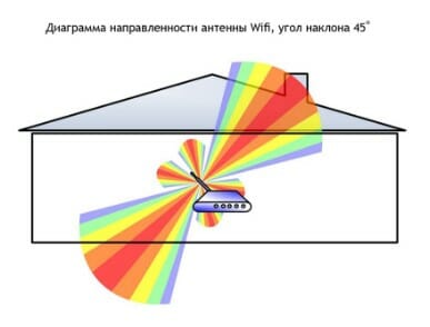
When the antenna is tilted relative to the horizon, part of the radiation is directed outdoors: dead zones form under the donut plane.

A vertically mounted antenna radiates horizontally: maximum coverage is achieved indoors.
On practice: Installing the antenna vertically is the easiest way to optimize your indoor WiFi coverage.
Place the router closer to the center of the room
Another reason for the occurrence of dead zones is the poor location of the access point. An antenna emits radio waves in all directions. In this case, the radiation intensity is maximum near the router and decreases with approaching the edge of the coverage zone. If you install an access point in the center of the house, then the signal will be distributed across the rooms more efficiently.
The router, installed in the corner, gives part of the power outside the house, and the distant rooms are on the edge of the coverage area.
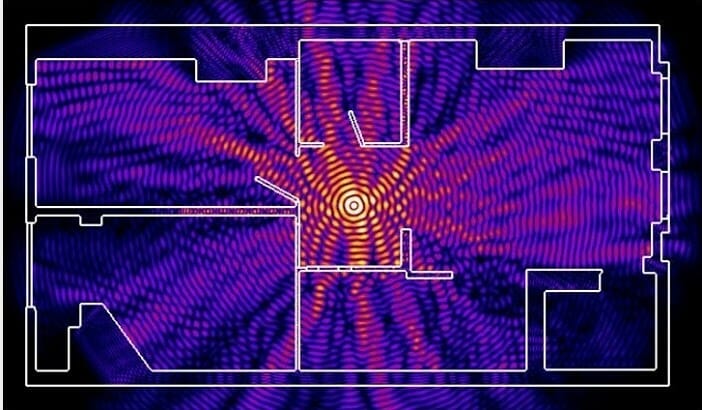
Installation in the center of the house allows you to achieve a uniform distribution of the signal in all rooms and minimize dead zones.
In practice: Installing an access point in the “center” of the house is far from always feasible due to the complex layout, the lack of outlets in the right place or the need to lay the cable.
Provide direct visibility between the router and clients
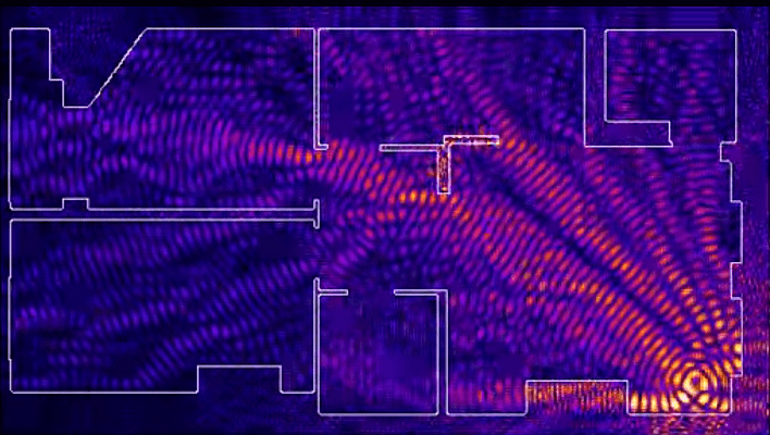
WiFi signal frequency is 2.4 GHz. These are decimeter radio waves that poorly envelop obstacles and have low penetrating power. Therefore, the range and stability of the signal directly depends on the number and structure of obstacles between the access point and the clients.

Passing through a wall or ceiling, an electromagnetic wave loses some of its energy.
The amount of signal attenuation depends on the material that the radio waves overcome.


* Effective distance is a value that determines how the radius of a wireless network changes in comparison with open space when an obstacle passes through a wave.
Calculation example: WiFi 802.11n signal spreads in line of sight at 400 meters. After overcoming the non-capital wall between the rooms, the signal strength decreases to 400 m * 15% \u003d 60 m. The second wall of the same type will make the signal even weaker: 60 m * 15% \u003d 9 m. The third wall makes signal reception almost impossible: 9 m * 15 % \u003d 1.35 m.
Such calculations will help to calculate the dead zones that arise due to the absorption of radio waves by walls.
The next problem on the path of radio waves: mirrors and metal structures. Unlike walls, they do not weaken, but reflect the signal, scattering it in arbitrary directions.
Mirrors and metal structures reflect and scatter the signal, forming dead zones.

If you move the interior elements that reflect the signal, you can eliminate the dead zones.
In practice: It is extremely rare to achieve ideal conditions when all the gadgets are in direct line of sight with a router. Therefore, in a real home, the elimination of each dead zone will have to work separately:
- find out what interferes with the signal (absorption or reflection);
- think about where to move the router (or interior item).
Place the router away from sources of interference.
The 2.4 GHz band does not require licensing and therefore is used for domestic radio standards: WiFi and Bluetooth. Despite the low bandwidth, Bluetooth is still able to interfere with the router.
Green areas - stream from a WiFi router. Red dots are Bluetooth data. The proximity of two radio standards in the same band causes interference, reducing the range of the wireless network.
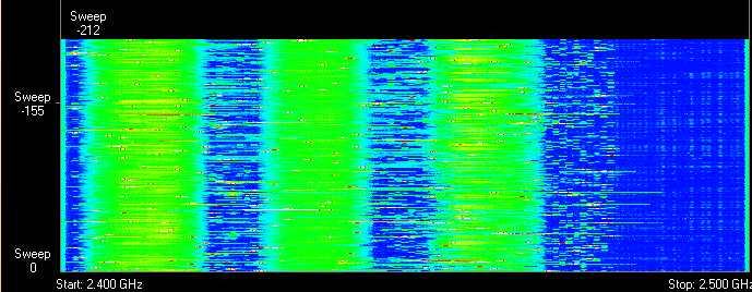
In the same frequency range, a microwave magnetron emits. The radiation intensity of this device is so great that even through the protective screen of the furnace, the magnetron radiation is able to “illuminate” the radio beam of the WiFi router.

Radiation from a magnetron in a microwave oven causes interference interference on almost all WiFi channels.
On practice :
- When using Bluetooth accessories near the router, we enable the AFH parameter in the settings of the latter.
- A microwave is a powerful source of interference, but it is not used as often. Therefore, if it is not possible to move the router, then simply during the preparation of breakfast it will not work to call on Skype.
Disable 802.11 b / g mode support
In the 2.4 GHz band, WiFi devices of three specifications work: 802.11 b / g / n. N is the latest standard and provides greater speed and range compared to B and G.

The 802.11n (2.4 GHz) specification provides longer range than legacy B and G.
The 802.11n routers support the previous WiFi standards, but the backward compatibility mechanics are such that when a B / G device appears in the coverage area of \u200b\u200ban N-router, for example, an old telephone or a neighbor's router, the entire network switches to B / G mode. Physically, the modulation algorithm changes, which leads to a drop in the speed and radius of the router.
In practice: Putting the router in “pure 802.11n” mode will definitely have a positive effect on the quality of coverage and throughput of the wireless network.
However, B / G devices will not be able to connect via WiFi. If it is a laptop or TV, they can be easily connected to the router via Ethernet.
Choose the optimal WiFi channel in the settings
Almost every apartment today has a WiFi router, so the density of networks in the city is very high. The signals of neighboring access points overlap each other, taking energy from the radio path and greatly reducing its effectiveness.

Adjacent networks operating on the same frequency create mutual interference interference, like circles on the water.
Wireless networks operate within range on different channels. There are 13 such channels (in Russia) and the router switches between them automatically.
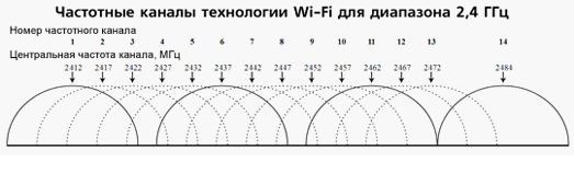
To minimize interference, you need to understand which channels the neighboring networks work on and switch to a less busy one.
Detailed instructions for setting up the channel are presented.
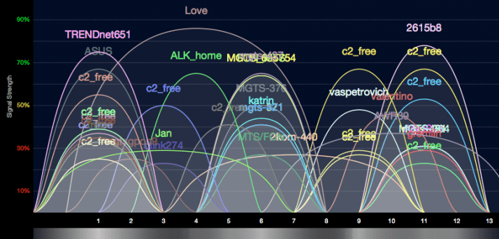
In practice: Choosing the least loaded channel is an effective way to expand the coverage area, relevant for residents of an apartment building.
But in some cases, there are so many networks on the air that not a single channel gives a tangible increase in the speed and range of WiFi. Then it makes sense to turn to method number 2 and place the router away from the walls bordering the neighboring apartments. If this also does not bring results, then it is worth thinking about moving to the 5 GHz range (method number 10).
Adjust the transmitter power of the router
The power of the transmitter determines the energy of the radio path and directly affects the radius of the access point: the more powerful the beam, the further it hits. But this principle is useless in the case of omnidirectional antennas of household routers: in wireless transmission there is a two-way data exchange and not only clients should “hear” the router, but also vice versa.
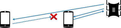
Asymmetry: the router “reaches” the mobile device in the far room, but does not receive a response from it due to the low power of the smartphone’s WiFi module. The connection is not established.
In practice: The recommended transmitter power is 75%. It should be increased only in extreme cases: the power twisted by 100% not only does not improve the signal quality in the far rooms, but even worsens the stability of reception near the router, because its powerful radio stream “clogs” the weak response signal from the smartphone.
Replace the standard antenna with a more powerful one
Most routers are equipped with standard antennas with a gain of 2-3 dBi. The antenna is a passive element of the radio system and is not able to increase the power of the stream. However, increasing the gain allows you to refocus the radio signal by changing the radiation pattern.

The higher the antenna gain, the further the radio signal spreads. At the same time, a narrower stream does not look like a “bagel”, but a flat disk.

There is a large selection of antennas for routers with a universal SMA connector on the market.


In practice: Using an antenna with high gain is an effective way to expand the coverage area, since the antenna sensitivity increases simultaneously with signal amplification, which means the router starts to “hear” remote devices. But due to the narrowing of the radio beam from the antenna, there are dead zones near the floor and ceiling.
Use signal repeaters
In rooms with complex layout and high-rise buildings, the use of repeaters is effective - devices that repeat the signal of the main router.


The simplest solution is to use an old router as a repeater. The disadvantage of this scheme is half the throughput of the daughter network, because along with the client data, the WDS access point aggregates the upstream from the upstream router.
Detailed instructions for configuring the WDS bridge are provided.
Specialized repeaters do not have the problem of bandwidth reduction and are equipped with additional functionality. For example, some Asus repeater models support roaming.

In practice: No matter how complicated the layout, repeaters will help you deploy a WiFi network. But any repeater is a source of interference. With free air, repeaters do their job well, but with the high density of neighboring networks, the use of relay equipment in the 2.4 GHz band is impractical.
Use 5 GHz band
Budget WiFi devices operate at a frequency of 2.4 GHz, so the 5 GHz range is relatively free and there is little interference.

5 GHz is a promising range. It works with gigabit streams and has increased capacity compared to 2.4 GHz.
In practice: “Moving” to a new frequency is a radical option, requiring the purchase of an expensive dual-band router and imposing restrictions on client devices: only the latest gadget models work in the 5 GHz band.
The problem with the quality of the WiFi signal is not always related to the actual range of the access point, and its solution in general terms boils down to two scenarios:
- In a country house, it is most often required in free broadcast conditions to cover an area that exceeds the effective radius of the router.
- For a city apartment, the range of the router is usually sufficient, and the main difficulty is to eliminate dead zones and interference.
The methods presented in this material will help identify the causes of poor reception and optimize the wireless network without resorting to replacing the router or the services of paid specialists.
Found a typo? Select the text and press Ctrl + Enter
Operating Systems